Digital strain measurement with the ESR x25 series Precise, robust, reusable
/ When offshore wind development in Germany picked up in 2010 with the commissioning of alpha ventus, experienced experts and pioneers in the industry were few and far between. Sensing the need to expand its expertise into this new market, leading international consultant Deutsche WindGuard set out to change the game. /

“Expertise in the matter of wind.”
Film-based strain sensors on the basis of strain gauges are currently the most widely spread sensor solution in metrology when it comes to measuring strains respectively loads in wind turbine generator (WTG) structures. The term ‘structures’ basically refers to all major components such as tower, machine/generator frame as well as rotor blades (figure 1). For more than 20 years this metrological technology has been applied to measurements addressing various issues:
● Testing prototype components and their design at test rigs.
● Certification and approval of installed wind turbine prototypes.
● Longterm monitoring of WTG structures over their service life
Sites of strain measurement.
Pos. 1: Rotor blade.
Pos. 2: Machine/generator frame.
Pos. 3: Tower.
The development is trending towards load-optimized WTG operation using permanently installed strain sensors. Since recently sensor systems have also been used on the basis of fibre optical metrology (FBG - Fibre Bragg Grating), at least for long-term monitoring of WTG rotor blades. Occasionally, they are also deployed in test rig applications.
However, in both sensor systems above, time and partly cost consuming subsequent electronics need to be used for the conversion into a digital signal. Strain sensors commonly use a combination of measuring amplifier + analogue-digital converter at each measuring point, while FBGs operate using an interrogator, which generates a digital signal from the changes in wave length resulting from the elongation.
Both sensor systems sharea high sensitivity to ambient conditions during installation and operation, which include for instance temperature influences and damages caused by blade adhesive residues or personnel. Consequently, extensive time-consuming safeguarding and compensation measures have to be taken at the measuring point. The sensors in use can typically be deployed just once; new sensors are thus required again for time-limited but recurring measuring campaigns.
A further new option for strain measurements is based on an electro-optical signal transducer/ encoder whose technology has been known, tried and tested in the wind industry and other sectors for decades in conjunction with position and speed detection of motor shafts. After a development and testing period of four years, the newly-designed proven encoder metrology cuts both ways: It significantly facilitates encoder measuring during installation and commissioning and also improves utilization regarding results in quality and reproducibility compared to the above-mentioned strain gauge and FBG.
The ESR x25 strain sensor series (figure 2) is adjusted to a large number of conceivable applications whether they be intended for permanent use in load-optimized turbine control or use in short-term measuring campaigns to detect design loads.
The essential properties are briefly stated in the following:
THE ESSENTIAL PROPERTIES ARE BRIEFLY STATED IN THE FOLLOWING:
- Mechanically tension free measuring principle with passive temperature compensation
- Because of the measurement arm length, arising material defects that can specifically occur in GFRP laminates locally only insignificantly feed into the measuring result.
- Bonding, screwing or magnet installation versions adaptable to the application
- Robust sensor configuration with slip proof housing made of aluminium, IP66 protection class and up to 40°C ....+100°C usage temperature
- Digital output signal at a resolution of 0.025 µε within a measuring range of +/ 5,000 µε and a mechanically permissible operation range of +/- 17,500 µε
- Builtin application-specific integrated circuit (ASIC) makes for a reproducible output signal, integrated temperature measurement, continuous condition monitoring, readable electronic type plate as well as access to a built-in sensor storage to store customer specific information
The ESR x25 series is based on a high-resolution and industrially manufactured encoder that uses the change in length of a reference distance of 200mm for strain measurement. To this end, two points at 200 mm distance from each other are attached at the object to be measured; one mounting point being on the rotary encoder axis, the other at the end of a measuring rod. By means of the relative change in length of the loaded measuring object to the parallel unloaded measuring rod, the encoder measures an angular change which serves to detect the change in length. On the basis of selected geometries one increment of the encoder corresponds to 5 nm change in length and/or 0.025 µε strain.
Corresponding to the measuring range of +/- 5,000 µε, this results in an available resolution of +/- 200,000 values or > 18bit, thus providing about 5x more measuring information than other commonly available strain gauge installations. The overall inaccuracy of the sensor is below +/- 10 µε throughout the whole measuring range. This can be reduced up to factor 5, if calibration factors stored on the sensor are recorded and computed in the subsequent electronics.
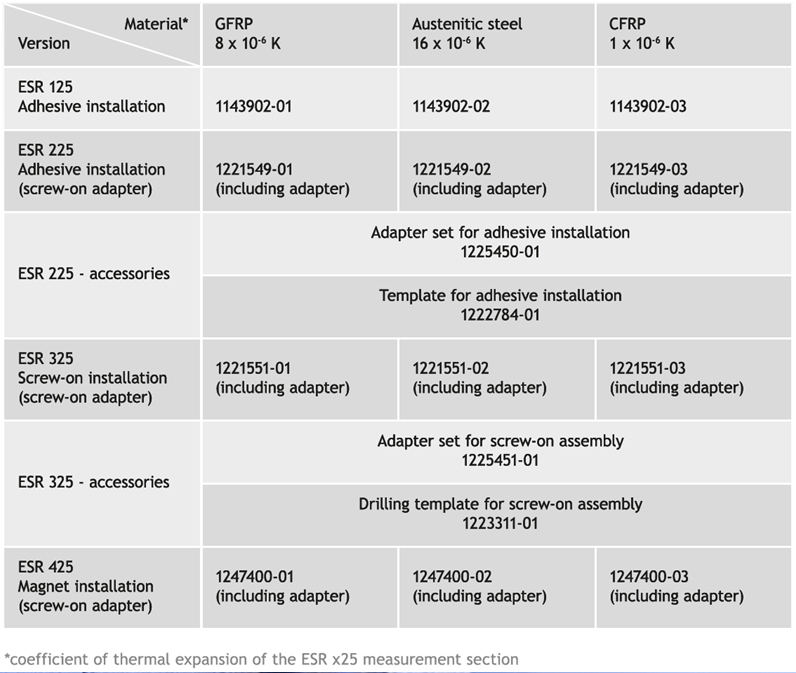
The passive temperature compensation is achieved by the constructive design of the sensor. The two measuring reference points are connected by a measuring rod that is made of the same material as the measurement object. Due to the same material-related thermal expansion coefficient, temperature-related strains are not measured.
The measuring rod can consist of various materials so that the expansion coefficient of the measuring rod can be adapted to the expansion coefficient of the measuring object, resulting in passive temperature compensation. In consequence, a temperature-related change in length leads to no expansion of the sensor that differs from the one of the measuring object thus making it possible to clearly separate force-induced elongations from thermal ones.
ESR x25 series.
Each sensor is measured in its measuring range before delivery and delivered with a Quality Check Certificate according to DIN 55 350-18-4.2.1. On customer’s request a Quality Check Certificate can equally be issued according to DIN 55 350-18-4.2.2 and a DAkkS Calibration Certificate according to DIN EN ISO/IEC 17025.
For the installation of the ESR x25 sensors great store was set by rapidity and process reliability (figure 3). Similarly as for strain gauges, care must be taken with the bonding version (ESR 125, ESR 225) that the surface to be bonded will be relatively even and grease free. Once the bonding position is marked, bonding is accomplished in very few steps. Installation at a measuring spot can be carried out by up to 50% faster compared to strain gauges, thanks to sensor size, simple installation aids and the robust housing with which the sensor is fitted.
The screw-mounted version (ESR 325) makes mounting even easier. With the help of a drilling jig/drilling template, four holes need to be drilled into the structure to be measured and provided with a thread. In the next step, the sensor is screwed to the structure using an adapter. The screw connection thus enables this sensor version to execute fast mounting and exchange.
Another version facilitates mounting the sensor to the surface to be measured by means of magnets (ESR 425). Just as for the other versions, only marking is required in order to determine the exact direction of measurement. Having done so, the sensor, which is provided with magnets, can be attached to the surface. Sole requirements for sufficient holding strength are good permeability of the measuring object and a smallest possible air gap between magnet and surface on which measurement is to be done. For short-term measurements on magnetic surfaces this is the preferred installation version, since the sensor can be reused unlimitedly.
Thanks to its highly integrated optical sensing in the encoder, the ESR x25 produces a high precision digital measurement signal with extremely low noise, while sophisticated mechanics ensures very good repeat precision.
The measuring signal is transmitted to the subsequent electronics via the digital EnDat 2.2 interface free of interferences and losses. Depending on the subsequent electronics selected, this can already be the system control directly, data logger or a fieldbus transducer, which if required collects a large number of ESR x25 signals and makes them available in a lean network structure.
For collection and/or conversion of the digital sensor signal, a wide range of subsequent electronics are available:
- single or multichannel gateways for conversion to CANopen, PROFINET, PROFIBUS, EtherNet/IP, POWERLINK, Ethernet
- WLAN adapter with OPC UA protocol + app for mobile terminal devices (iOS, Android)
- display devices, which reproduce the measuring signal directly on the screen
- DINrail modules for import into Automation Studio, LabView, TWINCAT
Moreover, work is ongoing on interfaces and configuration files for data logger and analysis tool providers represented in the market that enables simple as possible feed-in, reproduction and storage of measurement information for the user.
In short, sensors of the ESR x25 series provide an alternative option to the strain gauges used to date. However, thanks to the technology and design selected, they feature a multitude of additional options for straightforward, fast and yet high-precision measurement of strains in large structures.
“Technology at the highest level.”
/ It will push forward the organic integration of the offshore oil industry and the nuclear power industry /
contact information
/ It will push forward the organic integration of the offshore oil industry and the nuclear power industry /
Matthias Finke
Senior Product Manager
+49 (0)40 3176758 0


SHARE THE ARTICLE


